The Significance of Submerged Arc Furnace Diagrams
Creating a submerged arc furnace (SAF) diagram is a crucial preliminary step before manufacturing metal smelting equipment, as it paves the way for more efficient and safer operations. This article aims to delve into the importance of submerged arc furnace diagrams and their role in the production of various materials via the submerged arc furnace process.
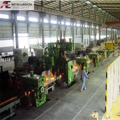
SAFs are vital pieces of equipment employed across a range of industries, including metallurgy, steelmaking, and chemical production. They operate through a distinctive process that involves melting raw materials beneath a layer of slag. To comprehend the functionality and operation of an SAF, a clear grasp of the submerged arc furnace diagram is essential.
The Role of Submerged Arc Furnace Diagrams
SAF diagrams offer a visual depiction of the various components and their spatial arrangement within the furnace. Typically, they include labels for the furnace body, electrode, electrode lifting mechanism, charging system, tapping system, and control system. This diagram aids engineers and operators in understanding the structure and function of the SAF.
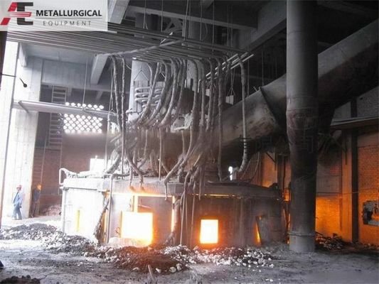
a) Furnace Body
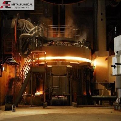
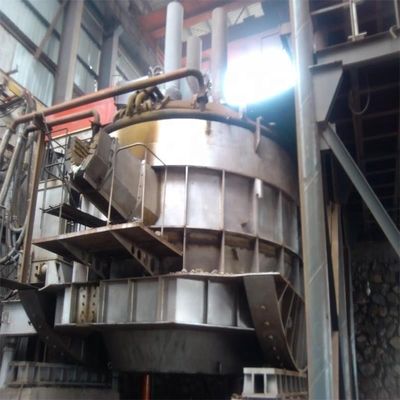
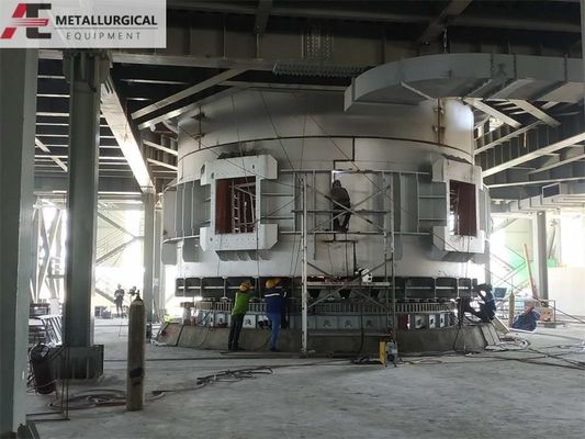
One of the key components illustrated in the submerged arc furnace diagram is the furnace body. This is where raw materials such as ore, flux, and carbon are loaded and melted. The diagram displays the shape and size of the furnace body, which can vary based on the specific requirements of the production process.
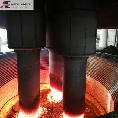
b) Electrode
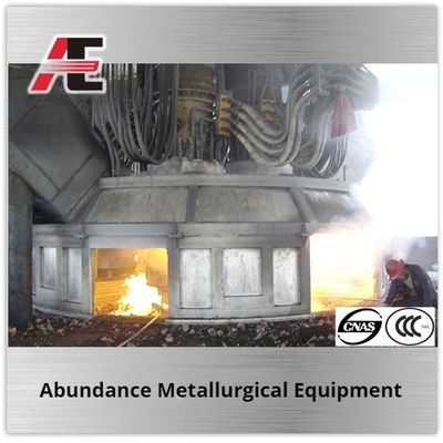
The diagram also highlights another crucial component of the submerged furnace—the electrode. Electrodes are responsible for transmitting the current to initiate the arc and provide the necessary heat for the melting process. The diagram shows the location and arrangement of the electrodes, as well as the electrode lifting mechanism that enables adjustments to the electrode position during operation.
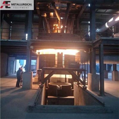
c) Charging System
Generally, the charging system is also depicted in the drawings. This system is tasked with introducing raw materials into the furnace. It may encompass a variety of equipment, such as hoppers, conveyors, and feeders, depending on the type and size of the material being processed. The design drawing clearly illustrates how the charging system is integrated into the overall SAF structure.
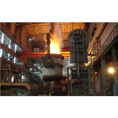
d) Tapping System
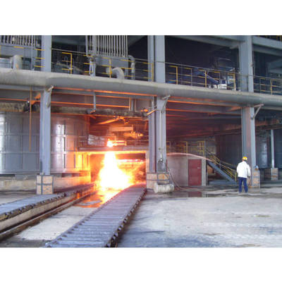
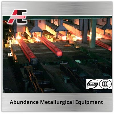
The tapping system shown in the diagram is utilized to extract the final product or slag from the furnace. It consists of tapping holes and channels, as well as tapping equipment like slag tanks or ladles. This diagram helps in understanding the location and arrangement of the tapping system, which is critical for safe and efficient operation.
e) Control System
Finally, the control system of the submerged arc furnace monitors and regulates various parameters, such as temperature, current, and feed rate. The diagram provides an in-depth understanding of the control mechanism and its integration into the overall furnace setup.
In conclusion, submerged arc furnace diagrams play a pivotal role in comprehending the structure and operation of this important industrial equipment. They offer a visual representation of the different components and their arrangement within the SAF, enabling engineers and operators to understand the complex processes involved.
By studying SAF diagrams, industry professionals can optimize the performance and efficiency of SAFs, thereby enhancing material production and improving overall process control.
We are a professional electric furnace manufacturer. For further inquiries, or if you require submerged arc furnaces, electric arc furnaces, ladle refining furnaces, or other melting equipment, please do not hesitate to contact us at susan@aeaxa.com

 Your message must be between 20-3,000 characters!